Accessing the SDPs on the i210
1 Introduction
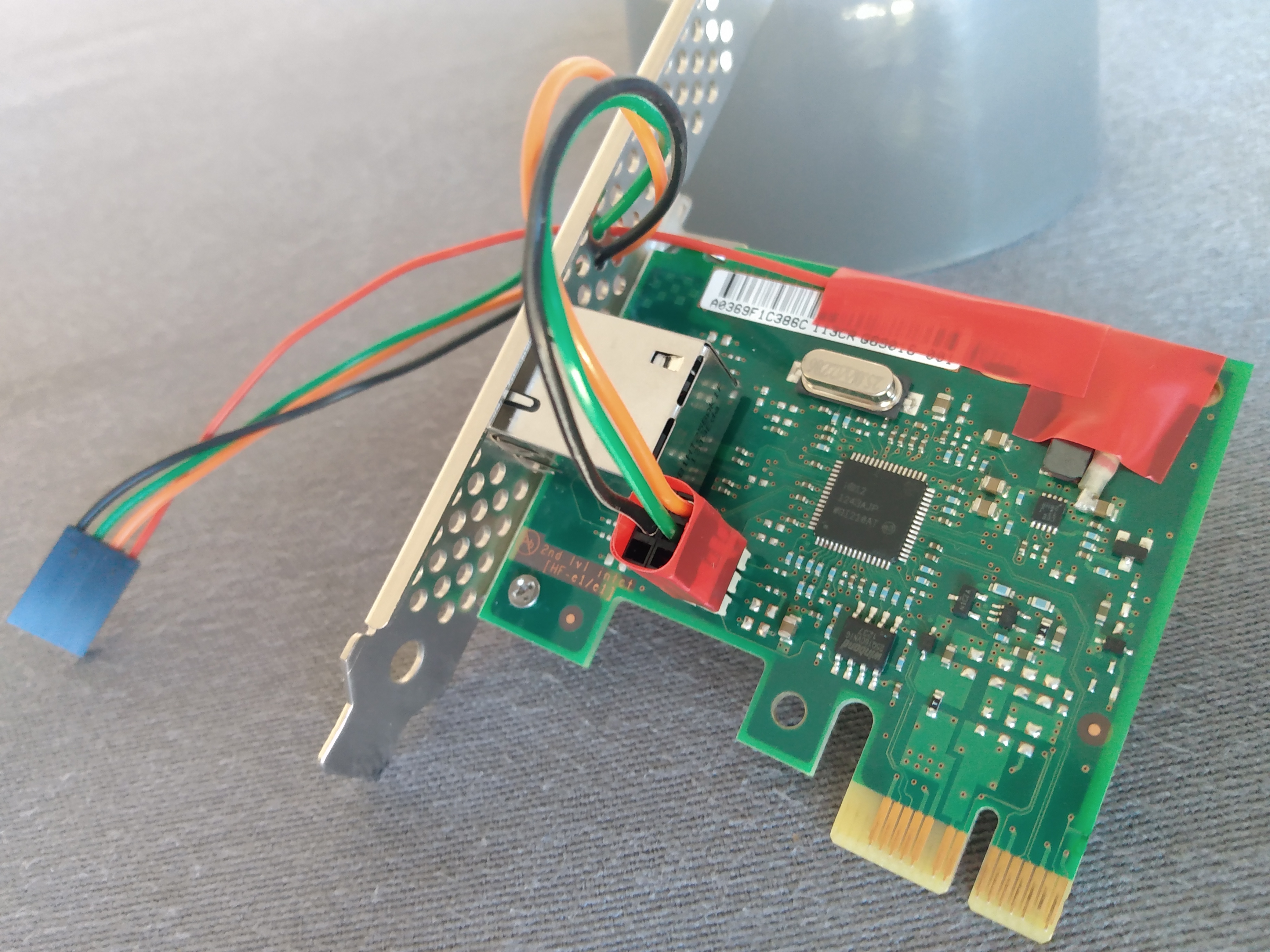
The Intel i210 Ethernet controller features four programmable pins, known as "Software Defined Pins" or SDP. Two of these pins are routed to a six pin header. With minimal rework, the card becomes a versatile, inexpensive PTP hardware testing solution.
2 Abbreviations
| DUT | Device Under Test | PPS | Pulse Per Second |
| GM | Grand Master | PTP | Precision Time Protocol |
| GPS | Global Positioning System | SDP | Software Defined Pin |
| PC | Personal Computer | TC | Transparent Clock |
3 Pinout of the Six Pin Header
4 Providing 3.3 Volt Power to a Transceiver
An RS232 transceiver may be used to electrically isolate the PC from the DUT. The device shown in Figure 2 requires power at the same voltage level as the input and output signals.
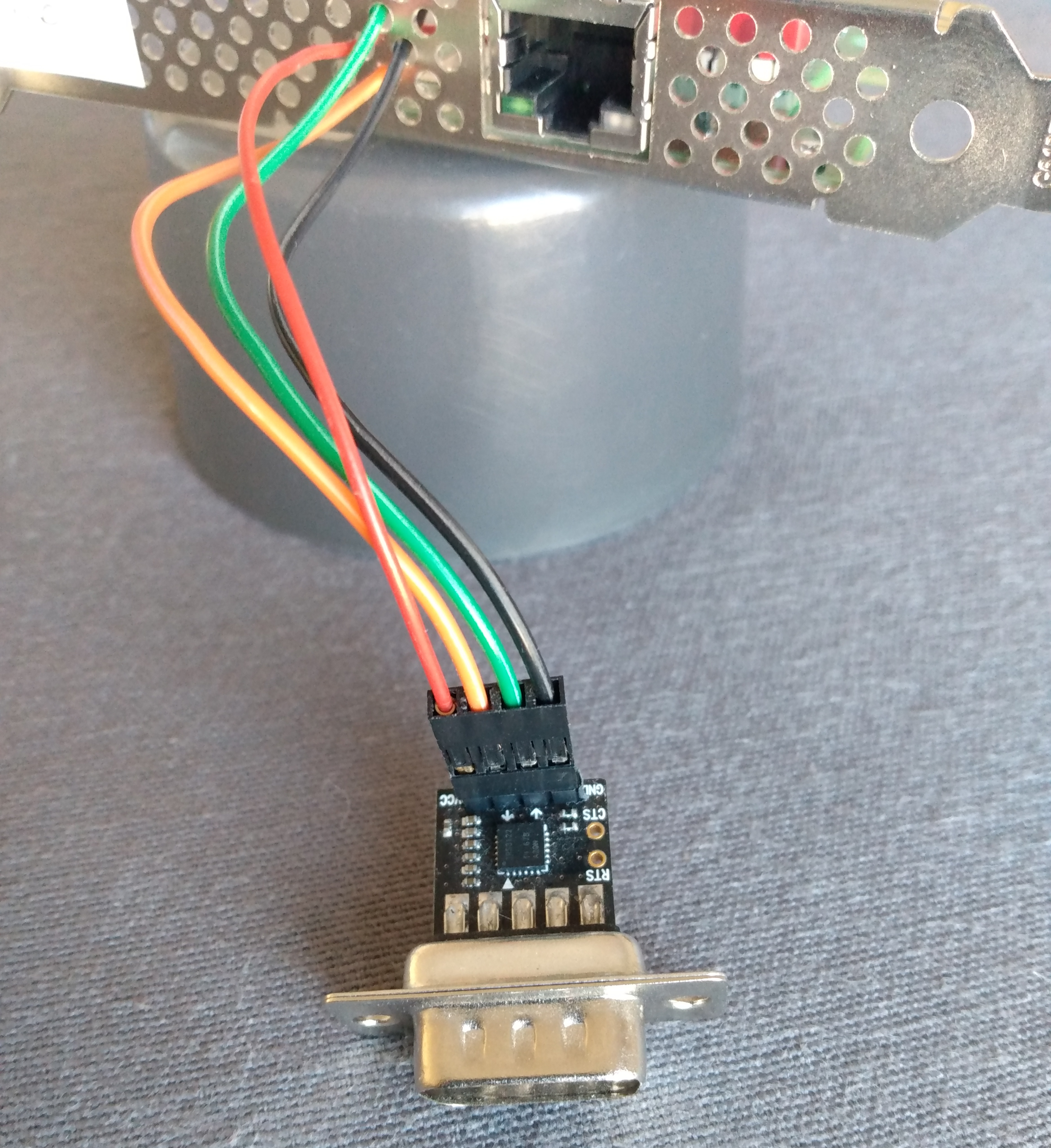
Figure 2: NulSom RS232 Transceiver
Unfortunately there is no convenient header from which to obtain 3.3 Volt power, and so the rework entails soldering a wire to a capacitor near the voltage regulator, as seen in Figure 1 on the upper right hand side. Figure 3 shows a close up view of the solder spot.
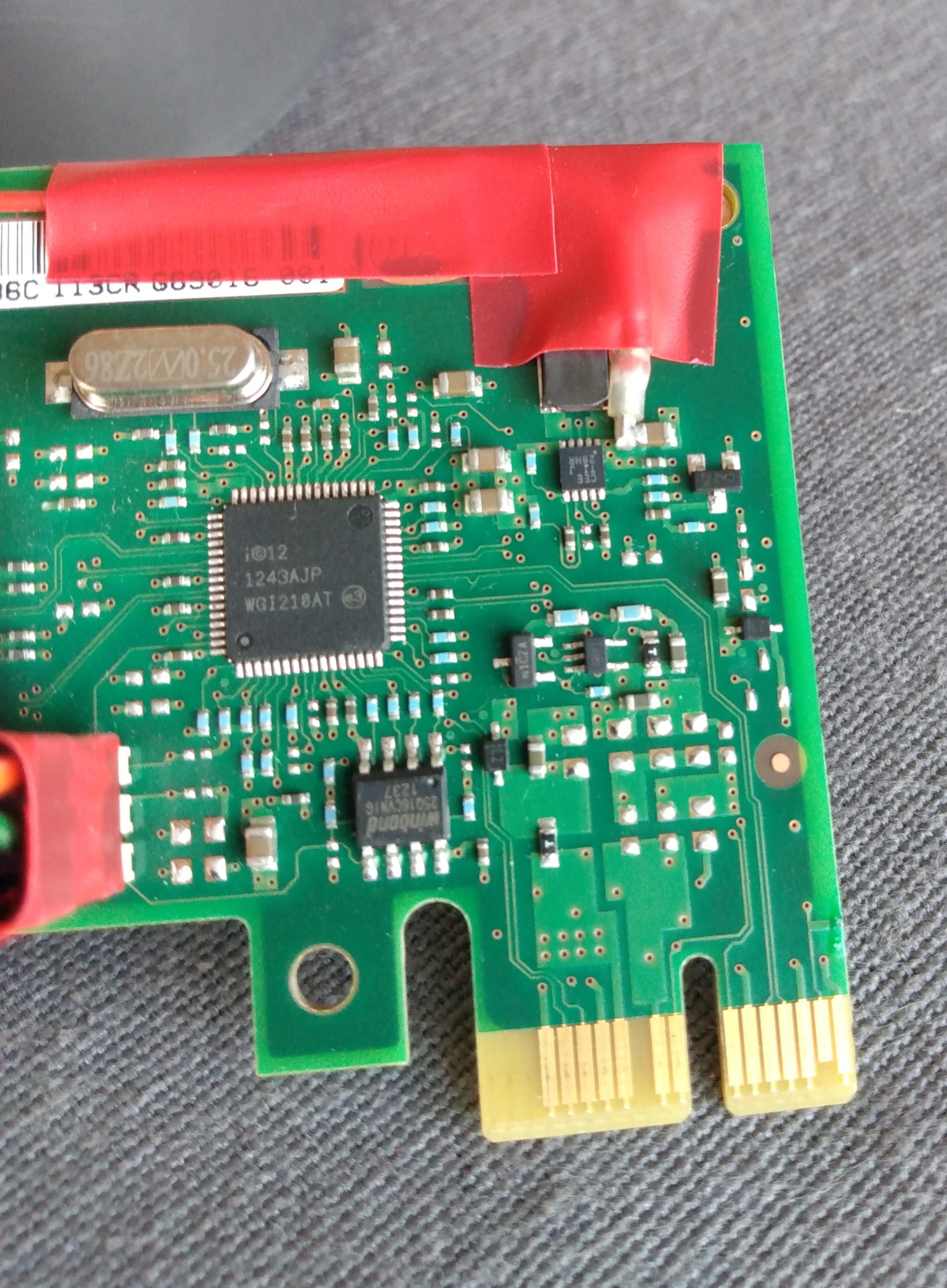
Figure 3: 3.3 Volt Power
5 Application Ideas
5.1 Single i210
PTP device testing
Connect the transceiver to a another transceiver on a DUT that can produce a 1-PPS signal. Configure SDP1 as an input. Use the PPS time stamps on SDP1 to characterize the DUT synchronization performance as a PTP server and as a PTP client.
GPS Grand Master clock
Connect the transceiver to a another transceiver on the PPS output of a GPS radio. Configure SDP1 as an input. Use the PPS time stamps on SDP1 to synchronize the i210 to the GPS time.
5.2 Multiple i210 cards
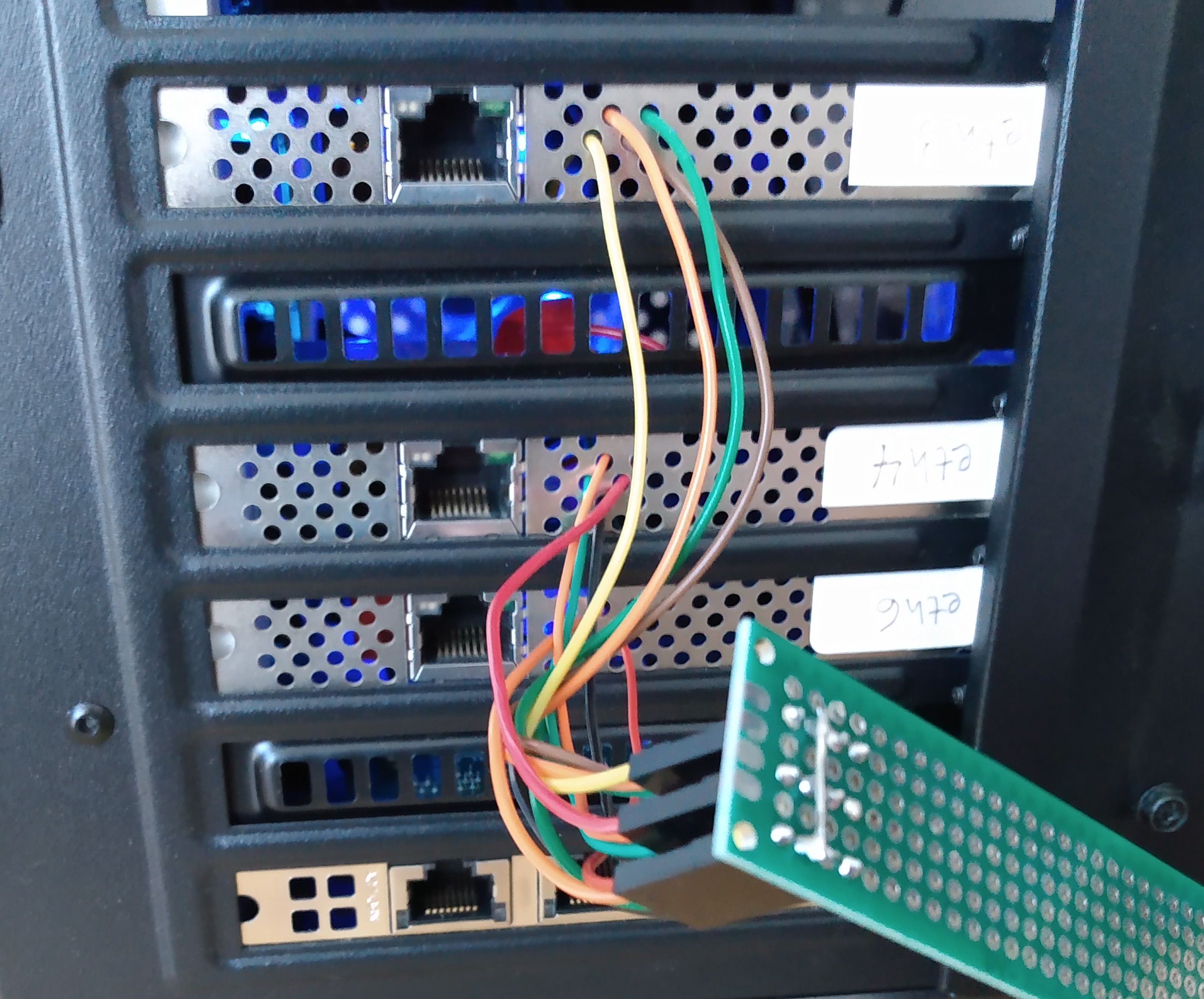
Figure 4: Test Machine with Three Cards
Two or more reworked i210 cards may be installed into one PC. Figure 4 shows a setup with three cards and a simple adapter to connect their SDP0 pins together directly, without using a transceiver. This only works when the grounds of the PCIe slots are tied together at the same level. Some PC motherboards have multiple PCIe buses with different ground levels! Using multiple cards opens up possibilities for additional test applications.
PTP network equipment testing
This method may be used to measure the synchronization performance of multi-port PTP devices such a Boundary Clocks and Transparent Clocks. Configure SDP0 on the first card as an output and let it generate a PPS output signal. Configure SDP0 on the other cards as inputs. Run a PTP time server on the first card's interface, and run PTP clients on the others.
First, connect the cards to the first card individually, using an Ethernet cable directly. Use the PPS time stamps on the SDP0 input to obtain the base line performance.
Then, connect the cards to the DUT. Use the PPS time stamps on the SDP0 inputs to measure the time error introduced by the DUT.
Transparent Clock
Use the
ts2phc-TC.cfgexample configuration from linuxptp and let thets2phcprogram synchronize the other cards to the first one. Run theptp4lprogram in TC mode on all the card's network interfaces.